
It follows the system voltage, not the capacity. A 35 kV nominal system needs 40.5 kV equipment, and KYN61-40.5 is the member of the series that covers that class; the others reach 24 kV at most. Typical places are the incomers, feeders and bus-ties of a 35 kV substation, the main intake substation of a large industrial park, and the step-up side of a wind or solar plant. Where the system is 10 kV and only the capacity is large, that is a rated-current question and KYN28A-12 or KYN550-12 fits better.
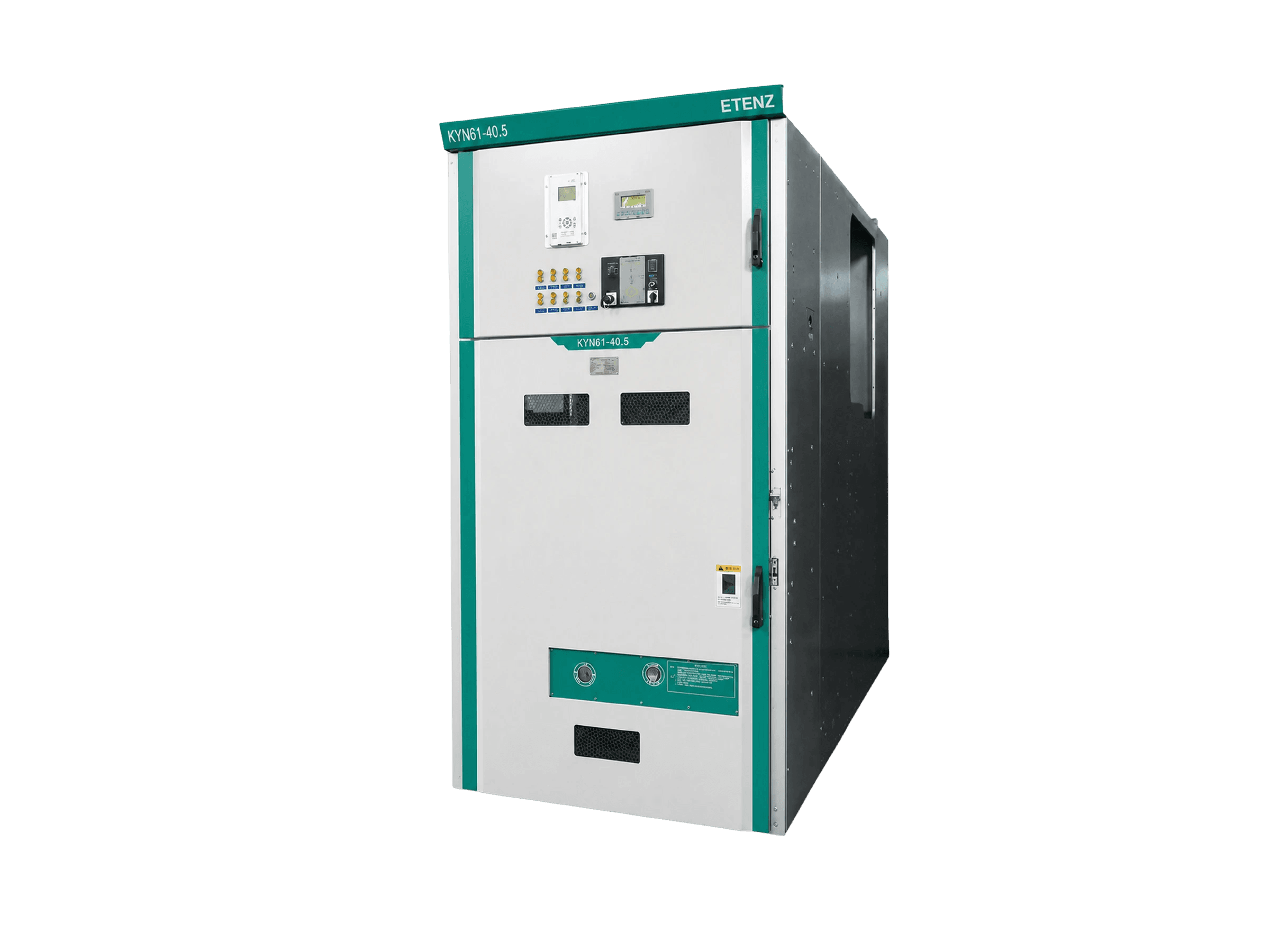
KYN61-40.5 Metal-Clad Withdrawable Switchgear
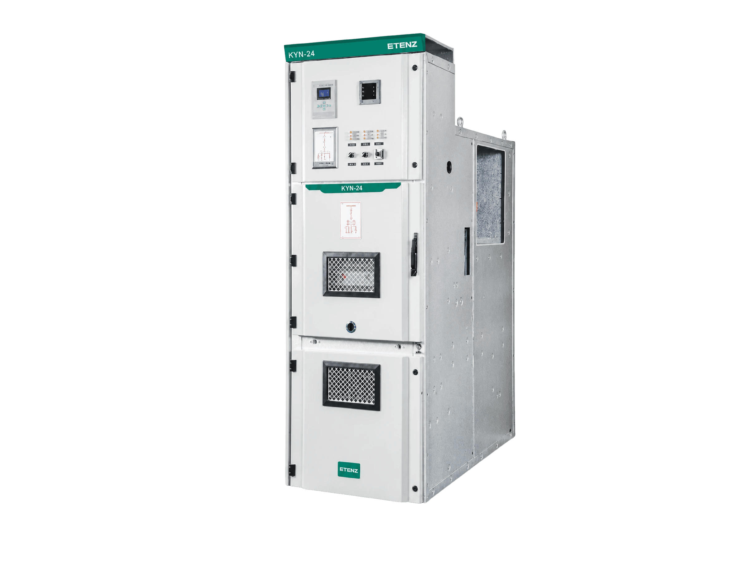
For 35 kV substations and industrial intake projects: KYN61-40.5 is the ETENZ metal-clad withdrawable switchgear rated 40.5 kV, 1250-2500 A rated current and 20-31.5 kA rated breaking current, supplied as a standard configured assembly or installed as the primary equipment inside an MV switchgear E-House.
Switchgear Room & Distribution RoomPrimary Equipment E-HouseRenewable Grid-Connection Power DistributionCampus Distribution Room
Key Metrics
40.5kV
Voltage
1250-2500A
Current
20-31.5kA
Breaking
IP4X
Protection
Product Features

40.5 kV class
The ETENZ KYN61-40.5 is the KYN member covering 40.5 kV, the others stopping at 24 kV and below. Rated current runs 1250 to 2500 A and rated breaking and 4 s short-time withstand 20 to 31.5 kA, for the incomers, feeders and bus-ties of a 35 kV system.
40.5 kV class
The ETENZ KYN61-40.5 is the KYN member covering 40.5 kV, the others stopping at 24 kV and below. Rated current runs 1250 to 2500 A and rated breaking and 4 s short-time withstand 20 to 31.5 kA, for the incomers, feeders and bus-ties of a 35 kV system.
40.5 kV class
The ETENZ KYN61-40.5 is the KYN member covering 40.5 kV, the others stopping at 24 kV and below. Rated current runs 1250 to 2500 A and rated breaking and 4 s short-time withstand 20 to 31.5 kA, for the incomers, feeders and bus-ties of a 35 kV system.

Insulation in pairs
Power-frequency withstand is 95 kV phase-to-phase and to earth and 118 kV across the isolating gap; lightning impulse is 185 kV and 215 kV respectively. The gap figure is higher than the to-earth figure by requirement of the withdrawable design, not as spare margin.

Two cubicle depths
The cubicle is 1400 wide and 2800 high, 2800 or 3000 mm deep, the 3000 mm option going with an SF6 truck. On 40.5 kV projects switchroom depth is usually the first thing to bind, so the depth is confirmed before the civil design is fixed.

E-House ready
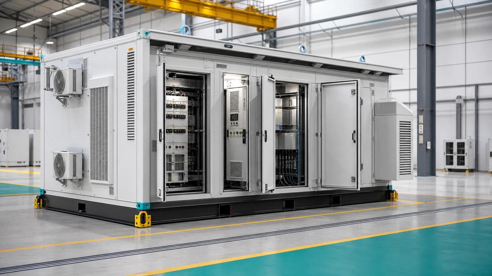
A KYN61-40.5 line-up can be delivered as the primary equipment inside an MV switchgear E-House or power module, with line-up arrangement, busbar connections and in-module interfaces detailed by ETENZ and the delivery boundary settled once at contract stage.
Product Details
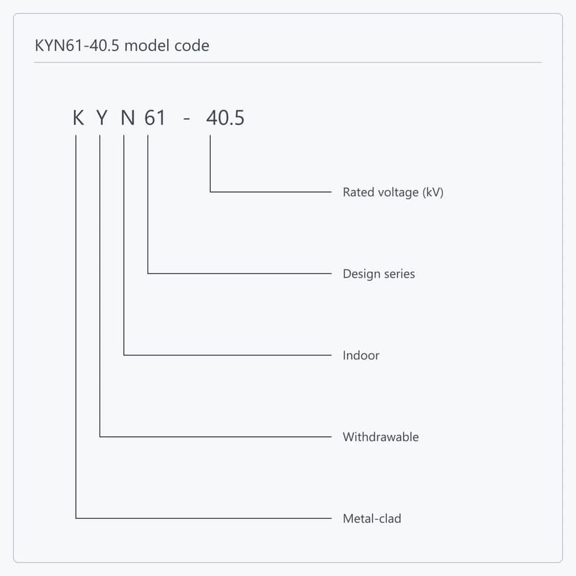
The identity part of KYN61-40.5 reads position by position: K is metal-clad construction, Y is the withdrawable pattern, N is indoor service, 61 is the design code and 40.5 is the voltage class. A complete order designation carries four more positions after it — primary scheme number, operating-mechanism code, rated current and rated breaking current. The first five fix the product identity; the last four fix the configuration of one cubicle, and are what a quotation is confirmed against.
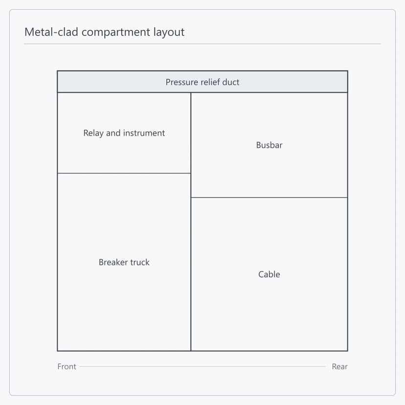
KYN61-40.5 follows the metal-clad withdrawable four-compartment structure — breaker truck, busbar, cable and relay-instrument compartments, each separated by metal partitions and each with its own independent pressure relief duct. At 40.5 kV every compartment grows: the cubicle is 1400 mm wide and 2800 mm high, the largest in the series, and the compartment scale in turn sets the front operating space and the truck withdrawal travel. The enclosure is aluzinc steel, CNC sheet-metal formed and joined with high-strength bolts and rivet nuts, with components powder coated or galvanised to the project requirement. ETENZ develops compartment dimensions, interlock travel and maintenance access against the confirmed cubicle type.
The depth in the parameter table reads 2800(3000), and the bracketed figure follows the truck type. With a withdrawable ZN85-40.5 (3AV3) vacuum circuit breaker truck the depth is 2800 mm; with an SF or FP-series SF6 breaker truck it is 3000 mm, while the 1400 mm width and 2800 mm height stay the same. Those 200 mm are often decisive in a 35 kV switchroom: the depth has to take the cubicle, the front operating and maintenance space and the truck withdrawal travel together, and changing it after the civil design is fixed is expensive. Breaker type and switchroom dimensions are therefore settled together. ETENZ calculates the line-up layout against the system data, the breaker type and the civil conditions.
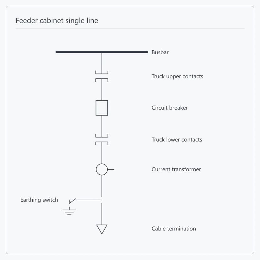
The primary circuit of a KYN61-40.5 feeder cubicle runs from the busbar through the upper truck contacts, the circuit breaker, the lower truck contacts, the current transformers and the earthing switch to the cable termination; incomer, bus-tie, metering and auxiliary-transformer cubicles add or remove devices on that basis. With 1250 to 2500 A rated current and 20 to 31.5 kA rated breaking and 4 s short-time withstand current, the type covers incoming and outgoing feeders and bus-ties in 35 kV substations, the main step-down substation of a large industrial park, and the step-up side of wind and solar plants. Circuit count, bus-tie and sectionalising arrangement and spare positions are settled at drawing approval.
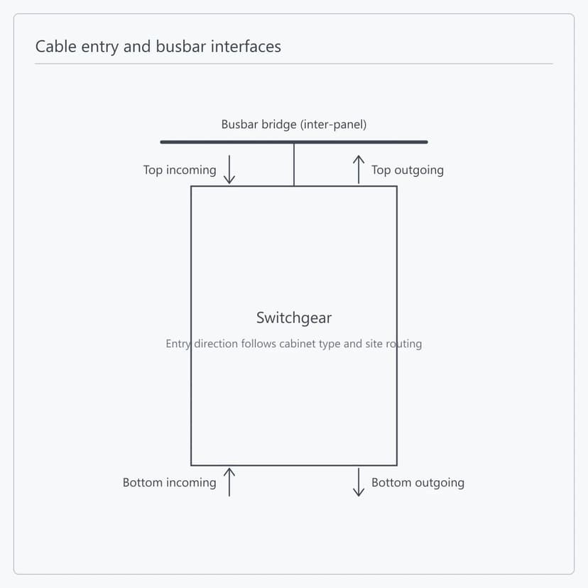
KYN61-40.5 accepts top entry with top exit, bottom entry with bottom exit and mixed arrangements; the direction follows the cable termination type and the routing on site. Busbar cross-section and phase spacing at 40.5 kV are both larger than on a 12 kV cubicle, so the roof busbar bridge and its supports grow accordingly and have to be calculated together with the switchroom head height and the lifting route. ETENZ fixes cable terminations, busbar connections, inter-panel links and earthing points on the drawings before manufacture, leaving only the connection work on site.
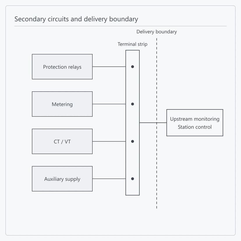
Protection relays, metering devices, CT/VT and auxiliary supplies are installed, wired and checked circuit by circuit in the works, with all secondary signals brought to one terminal strip; the mechanical and electrical parts of the five-prevention interlocking are completed at the same time. Everything beyond the terminal strip — the upper-level monitoring system, station control and external I/O — sits on the customer side, with interface type and protocol agreed at technical specification stage. The boundary is confirmed with the project drawings, and connection on site follows them.
Supply Scope and Delivery Boundary
All three apply to every order: what is supplied, how far secondary work goes at the works, and which inspection records and documents ship with the cubicles.
Single Cubicle or Complete Lineup Supply
Cubicles are supplied singly or as a complete lineup against the order schedule. Enclosure, main circuit and internal connections are assembled at the works and shipped as complete cubicles; where transport limits apply, the lineup is split and the joining interface is set beforehand. Where the cubicles are to arrive inside a prefabricated cabin, the E-House line takes on the enclosure, internal arrangement and cubicle fixing, and the switchgear is delivered as equipment housed within it.
This covers:
Single cubicle or complete lineup
Complete-cubicle shipment and split points
Joining and fixing interface
In-cabin delivery handled by the E-House line
Single Cubicle or Complete Lineup Supply
Cubicles are supplied singly or as a complete lineup against the order schedule. Enclosure, main circuit and internal connections are assembled at the works and shipped as complete cubicles; where transport limits apply, the lineup is split and the joining interface is set beforehand. Where the cubicles are to arrive inside a prefabricated cabin, the E-House line takes on the enclosure, internal arrangement and cubicle fixing, and the switchgear is delivered as equipment housed within it.
This covers:
Single cubicle or complete lineup
Complete-cubicle shipment and split points
Joining and fixing interface
In-cabin delivery handled by the E-House line
Technical Specifications
Product form
Indoor metal-clad withdrawable AC switchgear
Model
KYN61-40.5
Rated voltage
40.5
kV
Rated current
1250-2500
A
Rated breaking current
20 / 25 / 31.5
kA
Short-time withstand current (4 s)
20 / 25 / 31.5
kA
Peak withstand current
50 / 63 / 80
kA
Rated making current
50 / 63 / 80
kA
1 min power-frequency withstand (phase / earth)
95
kV
1 min power-frequency withstand (isolating gap)
118
kV
Lightning impulse withstand (phase / earth)
185
kV
Lightning impulse withstand (isolating gap)
215
kV
Main switch type
ZN85-40.5 (3AV3) vacuum circuit breaker, or SF / FP-series SF6 breaker
Insulation process
Heat-shrink insulation, epoxy coating
Enclosure material and joints
Aluzinc steel, CNC formed, high-strength bolts and rivet nuts
Component surface finish
Powder coating or galvanising
Compartmenting and pressure relief
Metal partitions with an independent relief duct per compartment
Degree of protection
IP4X
Dimensions (W x D x H)
1400 x 2800(3000) x 2800; 3000 depth with an SF6 truck
mm
| Parameter | Specification |
|---|---|
| Product form | Indoor metal-clad withdrawable AC switchgear |
| Model | KYN61-40.5 |
| Rated voltage | 40.5 kV |
| Rated current | 1250-2500 A |
| Rated breaking current | 20 / 25 / 31.5 kA |
| Short-time withstand current (4 s) | 20 / 25 / 31.5 kA |
| Peak withstand current | 50 / 63 / 80 kA |
| Rated making current | 50 / 63 / 80 kA |
| 1 min power-frequency withstand (phase / earth) | 95 kV |
| 1 min power-frequency withstand (isolating gap) | 118 kV |
| Lightning impulse withstand (phase / earth) | 185 kV |
| Lightning impulse withstand (isolating gap) | 215 kV |
| Main switch type | ZN85-40.5 (3AV3) vacuum circuit breaker, or SF / FP-series SF6 breaker |
| Insulation process | Heat-shrink insulation, epoxy coating |
| Enclosure material and joints | Aluzinc steel, CNC formed, high-strength bolts and rivet nuts |
| Component surface finish | Powder coating or galvanising |
| Compartmenting and pressure relief | Metal partitions with an independent relief duct per compartment |
| Degree of protection | IP4X |
| Dimensions (W x D x H) | 1400 x 2800(3000) x 2800; 3000 depth with an SF6 truck mm |
Product FAQs
Because in a withdrawable cubicle that gap has to hold on its own. Once the truck is racked to test or isolated position, one side of the gap is live and the other is not, and the insulation rests on that gap. If the gap withstand were set equal to the to-earth withstand, a switching overvoltage would break the gap down first and the isolation would be lost. The standard therefore sets the gap a step higher: 118 kV against 95 kV at power frequency and 215 kV against 185 kV on impulse. This is a structural requirement rather than spare margin, so the two sets are read together during selection.
The 3000 mm option goes with an SF6 truck and 2800 mm is the standard configuration, so the depth follows from the breaker type rather than being specified freely. What matters is checking the civil work first: at 1400 wide and 2800 high, the switchroom depth has to take the cubicle, the front operating and maintenance space and the truck withdrawal travel together, and this is what binds first on 35 kV projects. Send the switchroom layout with clear height, craneage route and transport height limit and the depth can be settled during quotation.
That is this model range: 1250 to 2500 A. At 40.5 kV the current for a given power is lower than in a 10 kV system, so 2500 A already corresponds to a substantial capacity and the range covers ordinary projects. Where a circuit genuinely needs more, it becomes a busbar and cubicle recalculation — send the circuit rating and system data with the enquiry.
The functional compartments are closed off from one another by metal partitions, and each has its own independent pressure relief duct — independence is the point: if fault pressure arises inside one compartment it is vented through that compartment own duct and does not pass through the neighbouring ones. The enclosure itself is aluzinc steel, CNC sheet-metal formed and then joined with high-strength bolts and nuts and rivet nuts, with components powder coated or galvanised to the project requirement. This describes the cubicle structure; the page makes no claim about any test or classification status.
Three things give a preliminary scheme: the single-line diagram, system nominal voltage and rated current, and the system fault capacity. For a contract-grade quotation, add the cubicle count with each primary scheme, control supply type and voltage, metering and protection requirements, cable entry arrangement and cable sizes, communication interfaces, switchroom dimensions and any depth limit, and the standards and document list for the destination market.
Yes. Switchgear is supplied as equipment while an MV switchgear E-House or power module is supplied as an enclosure — the first is the panel itself, the second covers the enclosure, equipment layout, auxiliary systems and interface integration. A 40.5 kV line-up is large, so in-module arrangement, maintenance space and truck travel are calculated during module design. Where KYN61-40.5 goes inside as the primary equipment, ETENZ works all of that out and the delivery boundary is settled once at contract stage.
Related Solutions
Prefabricated Infrastructure
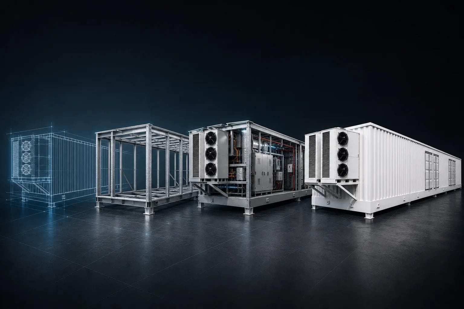
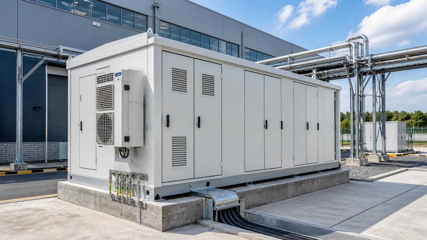
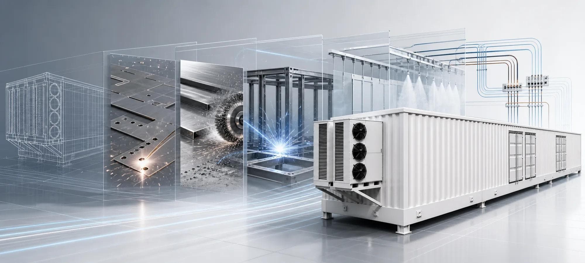
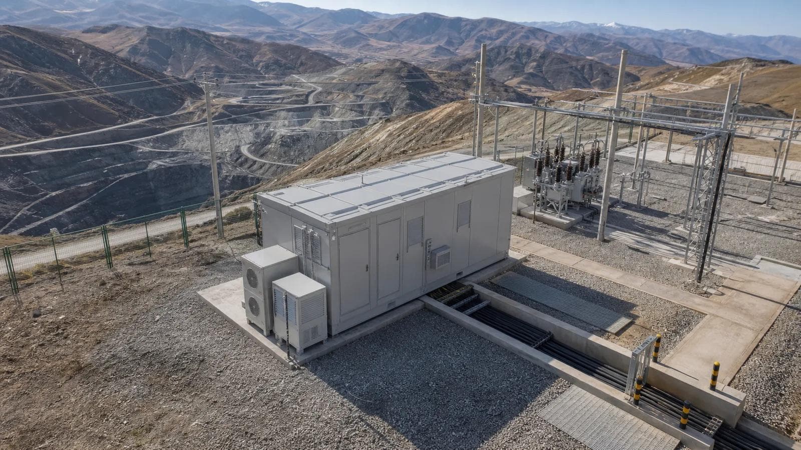
Prefabricated E-House Project Delivery Solution
ETENZ delivers configurable prefabricated E-House projects for electrical equipment integration, covering enclosure manufacturing, layout, wiring paths, factory checks, interface coordination, and OEM/ODM cooperation.
Product Application Cases


Related Products
Distribution Switchgear
Withdrawable Metal-Clad MV Switchgear - KYN Series
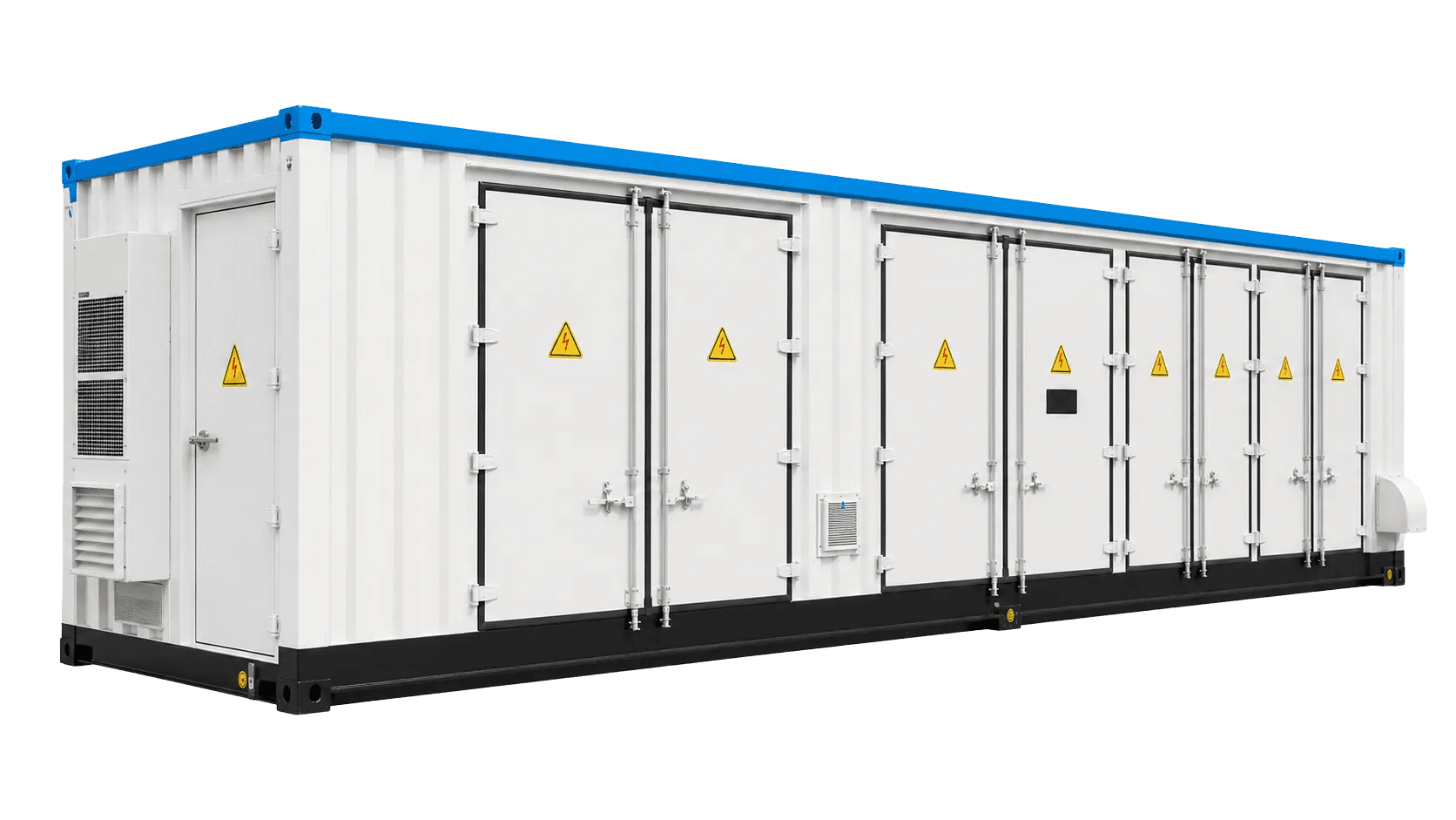
Electrical E-Houses
Containerized MV Switchgear E-House
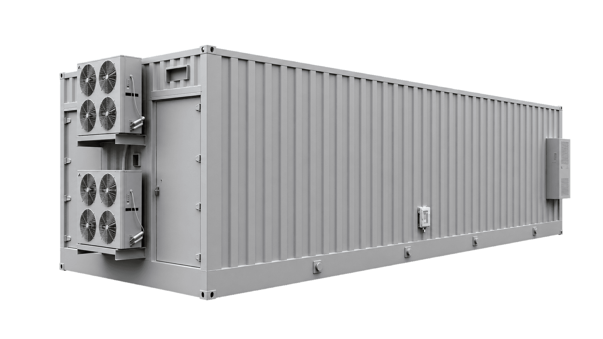
Electrical E-Houses
MV Switchgear E-House
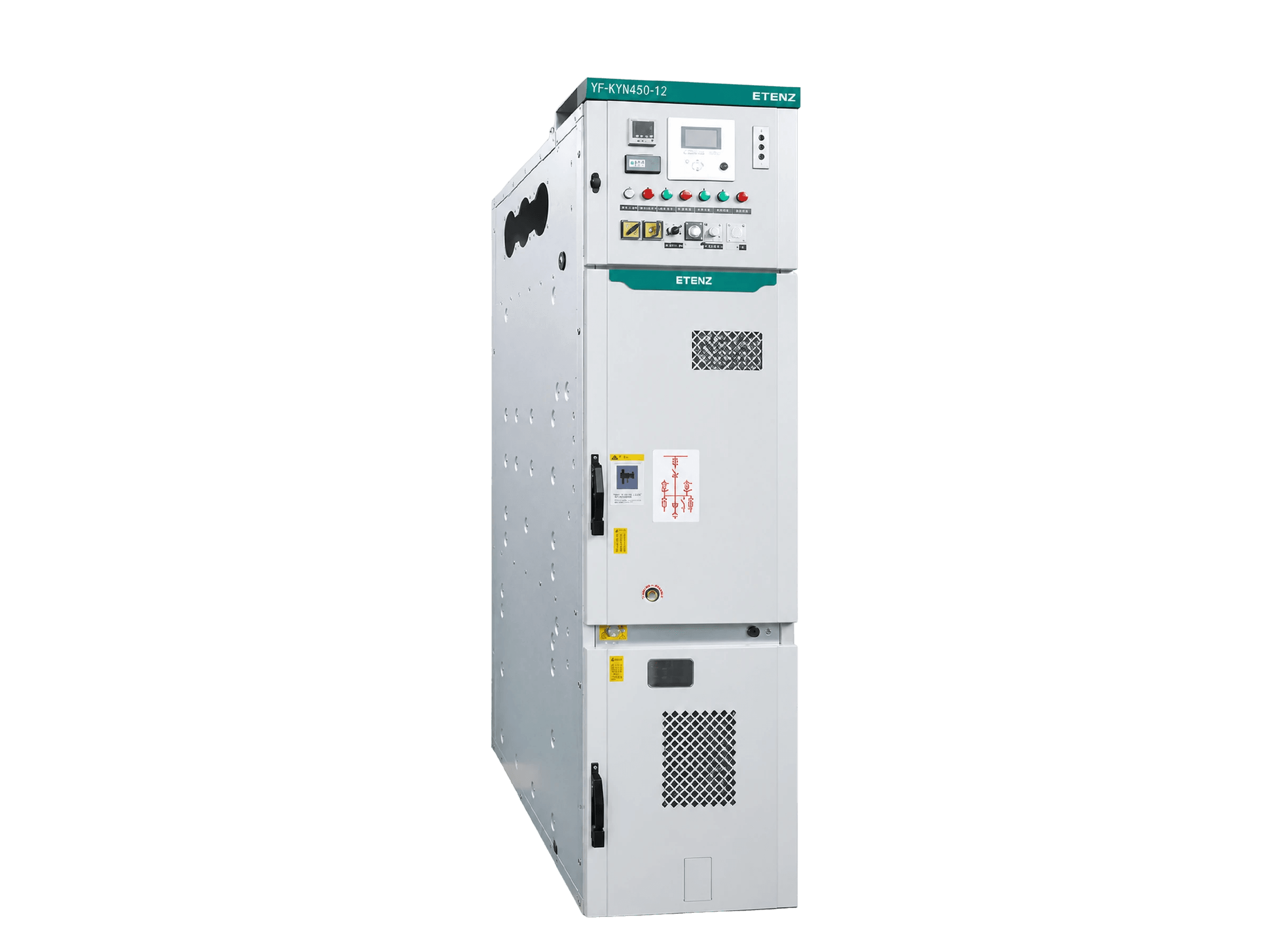
Distribution Switchgear
YF-KYN450-12 Compact Withdrawable Switchgear
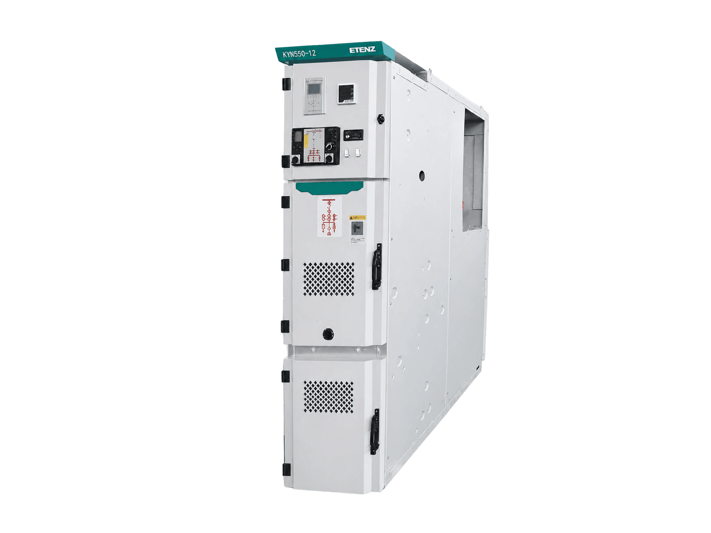
Distribution Switchgear
KYN550-12 Metal-Clad Switchgear
Distribution Switchgear